


Einbauanleitung Artikel 661: Verstellplatte für Spur- und Sturzeinstellung an der Hinterachse – Passend für VW Golf 2 & 3 Syncro bei Tiefer- oder Höherlegung
Installation instructions Article 661: Adjustment plate for toe and camber adjustment on the rear axle - Suitable for VW Golf 2 & 3 Syncro for lowering or raising
Initial situation: Why a camber & toe adjustment is necessary
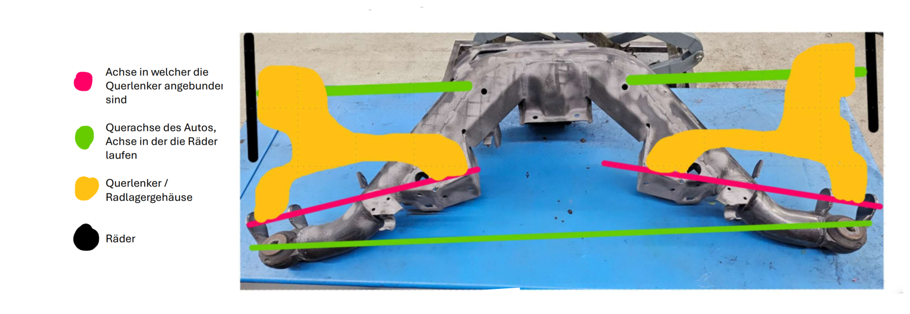
Vehicles such as the VW Golf 2 or 3 Syncro have a special design on the rear axle: the wishbones also act as wheel bearing housings, and the mounting points of these wishbones are not on the same axle as the wheels. This design imposes a number of design-related restrictions - particularly when the vehicle height is changed. If the vehicle is lowered, the rear wheels tilt inwards at the top (negative camber) and are positioned in relation to each other in the direction of travel. At the same time, the entire wheel position moves towards the rear. It is not possible to adjust the toe and camber at the factory, as the wishbones only have fixed screw points. This means that the wheel values are only in the optimum range in standard condition - any change in height leads to sub-optimal driving conditions.
Advantages of the conversion and important preparations
The camber and toe adjustment kit from Epytec provides a lasting solution to this problem. The adjustment plates make it possible to bring the toe and camber values back into the ideal working range for both lowering and raising. Alternatively, the wheel position in the wheel arch can also be influenced by specific adjustment - for more extreme camber values, for example. However, the conversion should not be underestimated: It requires extensive preparation, precision and technical understanding. Suitable tools and experience in welding (MIG or TIG) are also essential. Anyone with the necessary know-how will be rewarded with significantly improved driving behaviour.
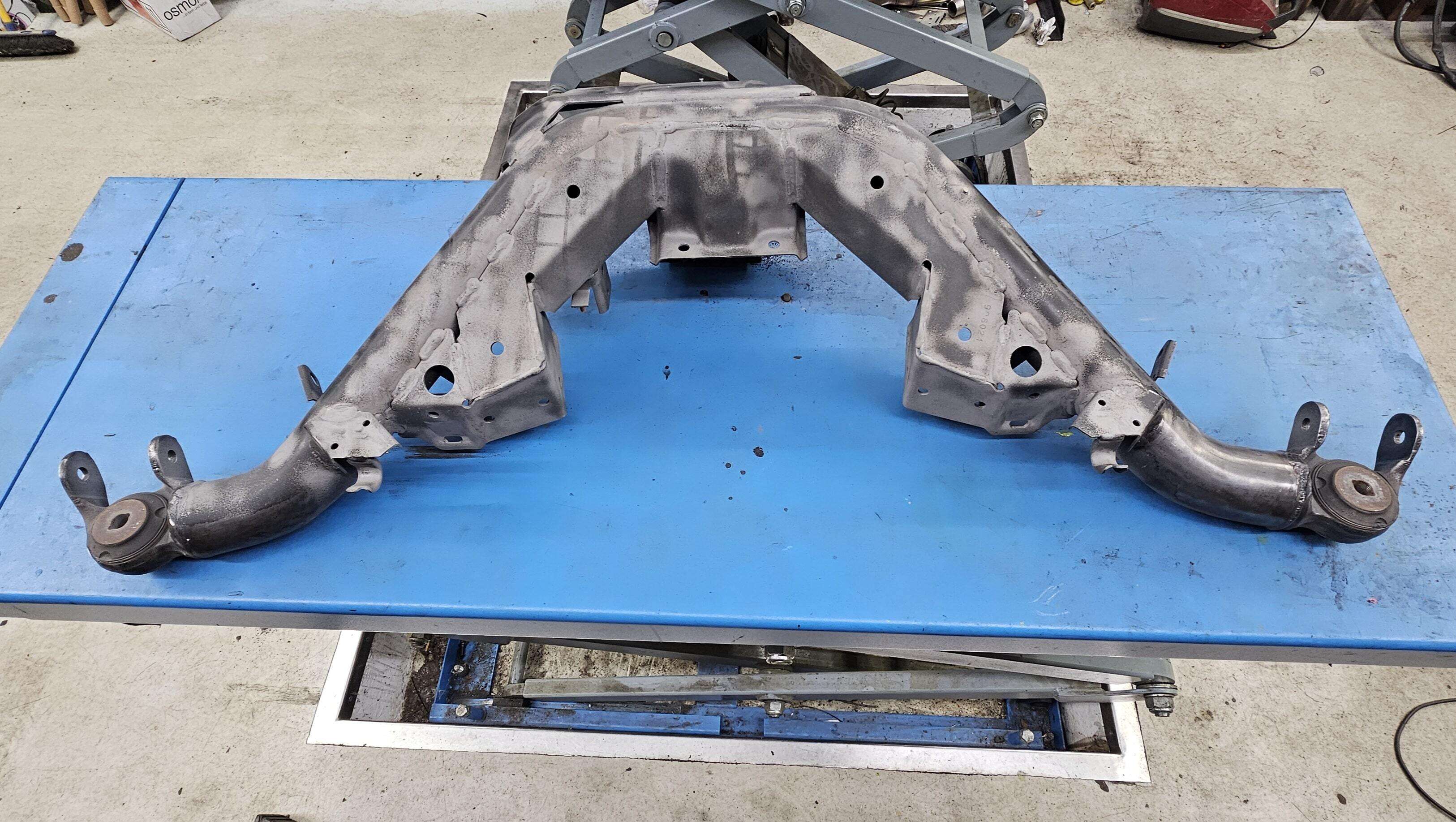
A completely dismantled and disassembled rear axle subframe is required to carry out the conversion. This must be completely derusted and any coatings, wax and paint residues must also be removed in the area of the subsequent welding points - ideally using a sandblasting machine. After the welding work, comprehensive corrosion protection, such as powder coating or high-quality painting, is absolutely essential. Tools required include a welding machine, various drills and milling cutters, gripping pliers, a cordless screwdriver, square and spirit level, a multi-function tool with milling attachments, angle grinder with wire brush and measuring tools.
Tools & materials
You will need a clean and well-prepared workshop environment and the following tools for the conversion:
-
Drill or cordless screwdriver
-
Step drill (e.g. 8-20 mm)
-
Multifunction tool with milling attachment
-
Welding machine (MIG or WIG recommended)
-
Welding tongs and screw clamps
-
Spirit level & angle
-
Caliper & steel measure
-
Angle grinder with cutting disc & wire brush
-
Tools for rust removal (e.g. sandblasting unit)
-
medium-strength threadlocker
-
Corrosion protection
Attention: The conversion requires very precise work and welding experience. Anyone who feels unsure about MIG/WIG welding should consult a specialised company!
Step 1: Preparing the subframe
Ihe first step is to thoroughly prepare the subframe. Rust and old paintwork must be completely removed - preferably by sandblasting. In many cases, the two-part barrel bearings are worn. They can either be removed directly or used as rough measuring points for the time being. If they need to be reused, they must be removed before welding work begins. A helpful tip: The heat generated during welding often makes it easier to loosen the steel sleeves of the bearings than when they are cold. For the conversion, it is advisable to organise the work area sensibly. The tools should be within easy reach and the frame should be positioned in such a way that you can work without tiring - for example on a lifting platform or stable trestles. As the frame has to be rotated several times, sufficient space is crucial.
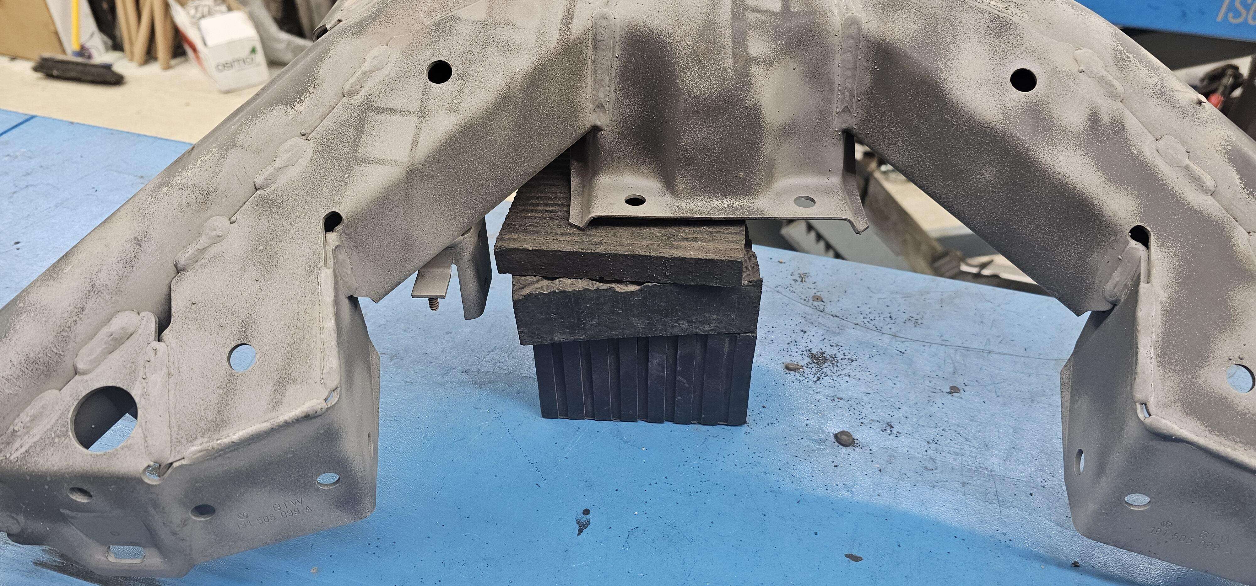
Step 2: Aligning the frame
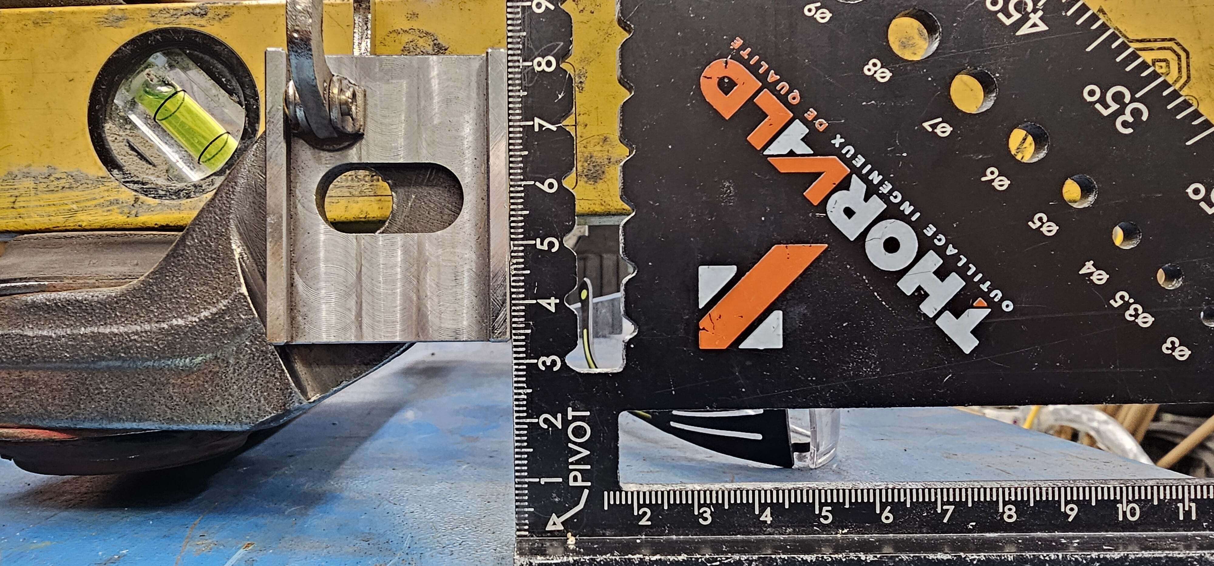
Correct alignment of the subframe is the basis for all subsequent steps. The frame must be positioned on the work surface exactly as it will later be installed in the vehicle. To do this, it is underlaid with rubber blocks. The parallelism of the top and bottom of the barrel bearing mount to the work surface serves as a benchmark - this can be checked using a spirit level and angle. The absolute height may vary slightly depending on the vehicle model (e.g. Golf 2, Golf 3 or Passat), as different barrel bearing diameters have been installed. However, only the exact parallelism is decisive for the subsequent marking of the drill holes.
Step 3: Marking the slotted holes for the track adjustment of the outer mounting points of the control arm
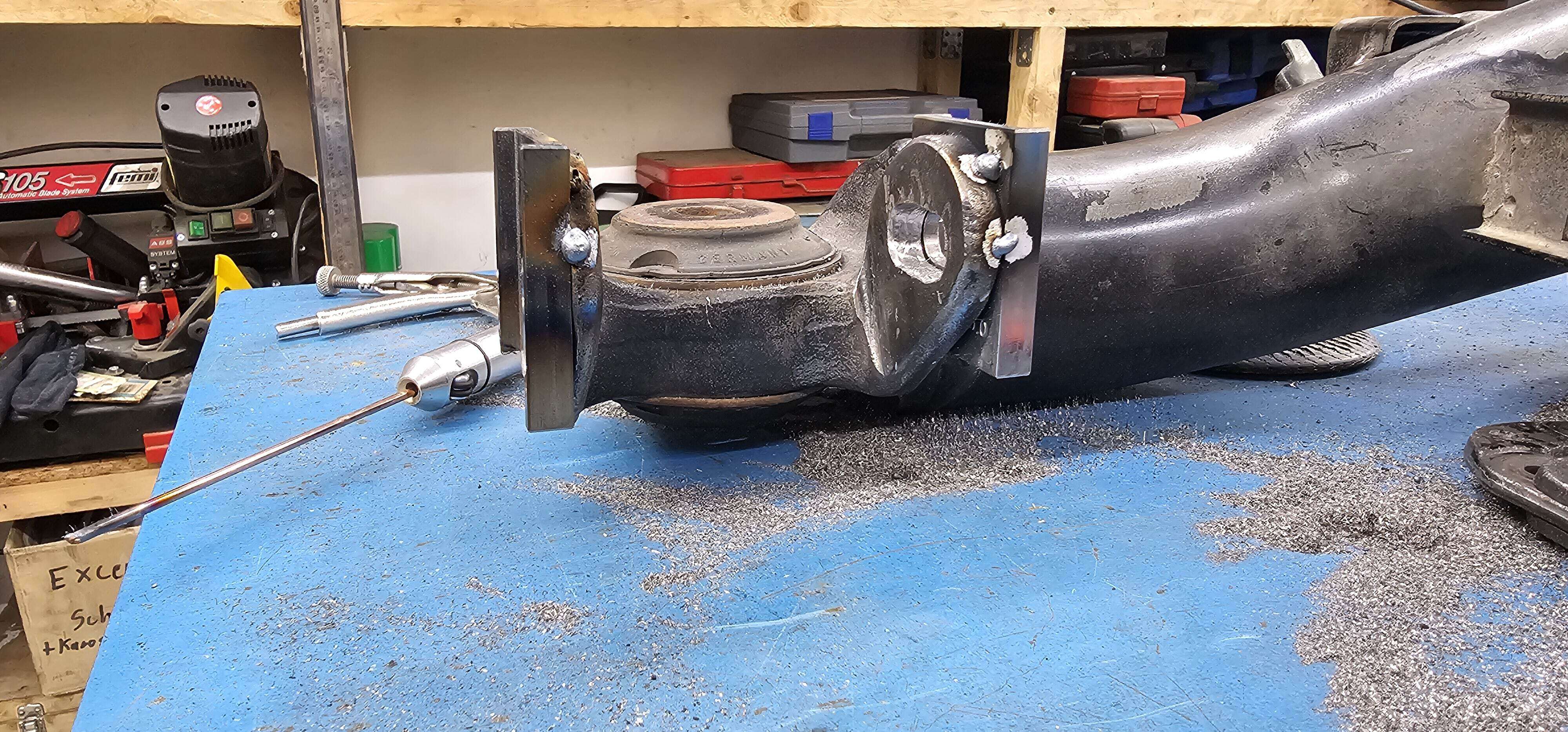
Once the subframe is correctly aligned, the two outer adjustment plates for the track adjustment can be fixed to the outer wishbone mounts using grip pliers. Ensure that they are aligned vertically (90° to the work surface). This allows the horizontal drilling height for the slotted holes to be marked. The end points of the slotted holes are not yet defined in this step - these will follow in the next phase. It is important that both panels are precisely aligned with each other to ensure even adjustment later on.
Step 4: Fixing and drilling the slotted holes (track adjustment)
To bring the panels into their final position, one corner of each panel must first be cut off. The final position on the frame can then be precisely marked. This determines the later usable adjustment range of the track and the exact wheel position in the wheel arch. The further back the plate is positioned, the more the range can be shifted from toe-in to toe-out - although the wheel will move further towards the rear. For a good balance, it is advisable not to utilise the maximum toe-out distance. The slotted holes are cut using a combination of step drills and small milling attachments (e.g. for the multi-function tool). A tried and tested method is to pre-drill the holes and then cut them out cleanly.
Step 5: Welding the track adjustment plates to the outer mounting points of the control arm
Once the slotted holes have been milled to fit, the track adjustment plates are welded together. To do this, the plates must be carefully aligned again and fixed in place with grip pliers. To prevent displacement during welding, the plates should first be tacked all round with spot welds before the complete seam is made. TIG welding in pulse mode is the recommended welding method. As the material has different thicknesses, the amperage, gas supply and nozzle size should be adjusted individually - depending on the material used and the welder's experience.
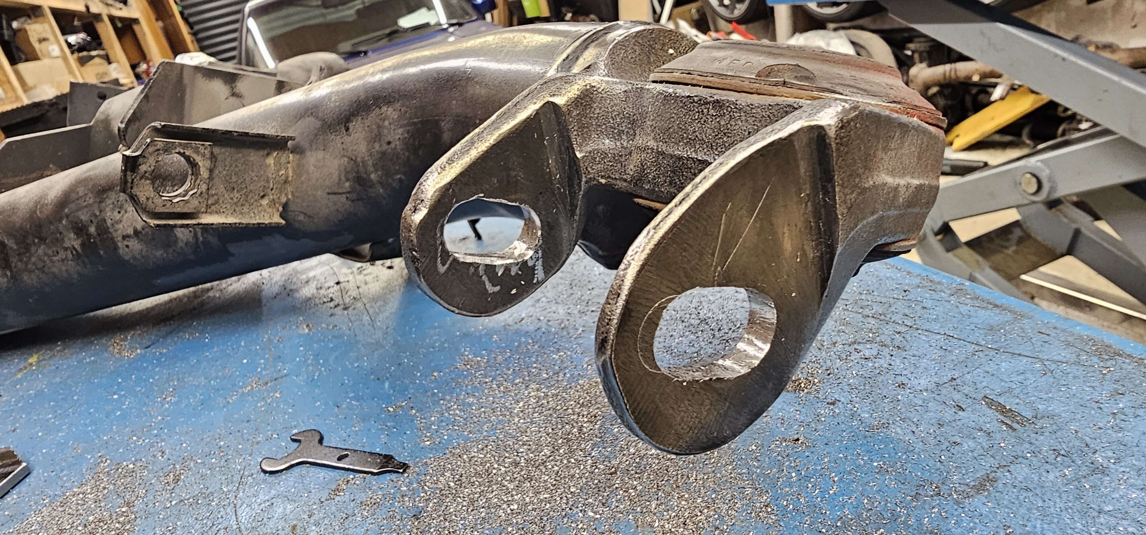
Step 6: Marking the slotted holes for the camber adjustment of the inner mounting points of the control arm
Positioning the inner plates for the camber adjustment is more complex, as the available space is much more limited. For space reasons, the inner plates must be shortened to around 43 mm - the cut may only be made on one side. The panels are positioned so that their lower edge is parallel to the lower edge of the axle. As the frame is rotated by 180° in this view (the axle is at the top), a higher position of the plate has a positive effect on adjusting the camber in a positive direction. This method allows a maximum neutral camber to be achieved if the lowering is high - if the lowering is low, a lower positioning of the plate also makes sense.
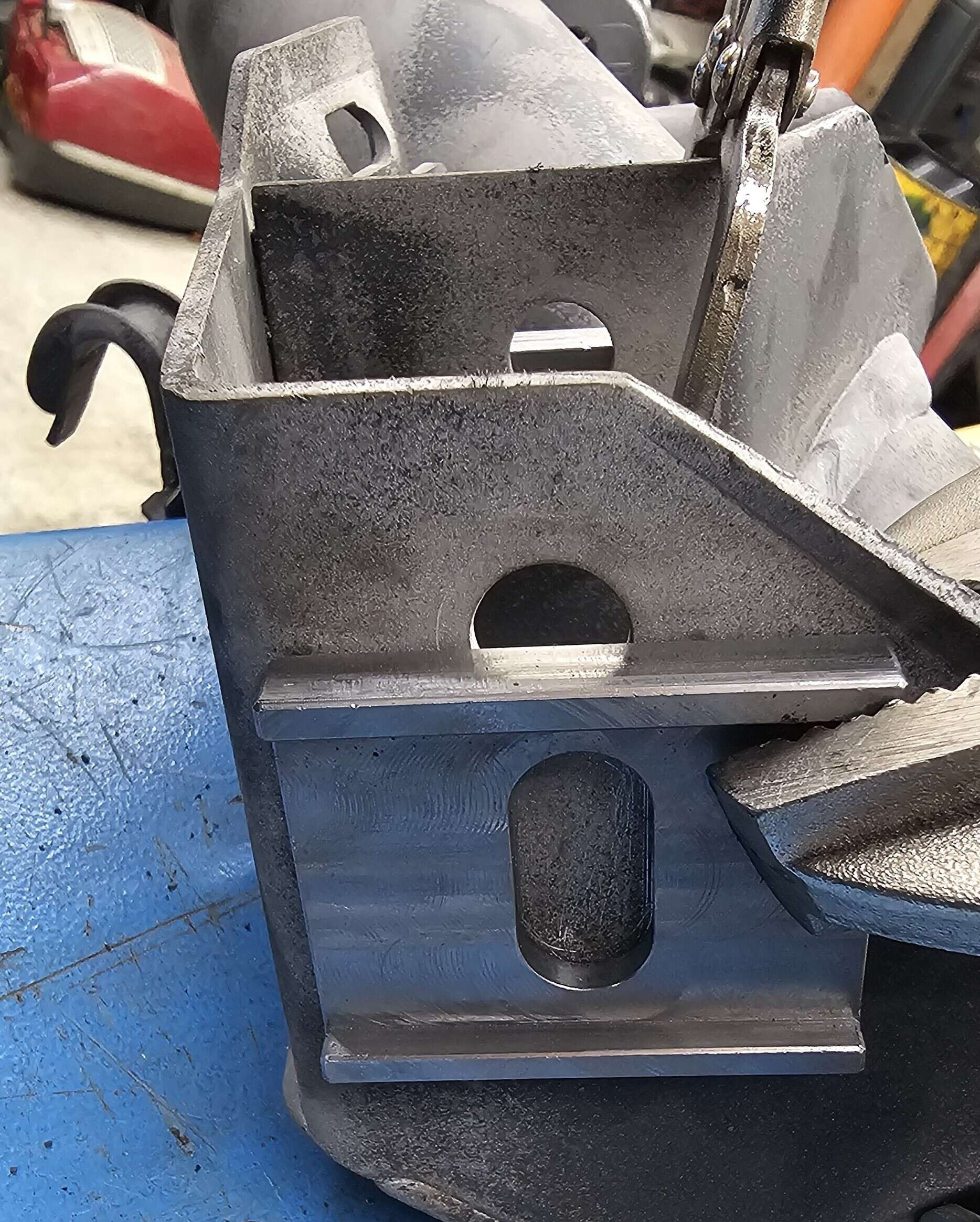
Step 7: Drilling the slotted holes and closing old holes if necessary
The same procedure applies to the holes for the camber adjustment as for the toe adjustment: pre-drilling with step drills, reworking with milling cutters. Depending on the position selected, the new slotted holes may overlap with the factory holes or lie directly next to them. In such cases, it is essential that the old holes are sealed to ensure the structural integrity of the frame. In many cases, it would also be possible to include the existing holes - however, this would usually maintain a negative camber of around -2°. If a more precise adjustment is required, new positions must be defined and the old holes professionally closed.
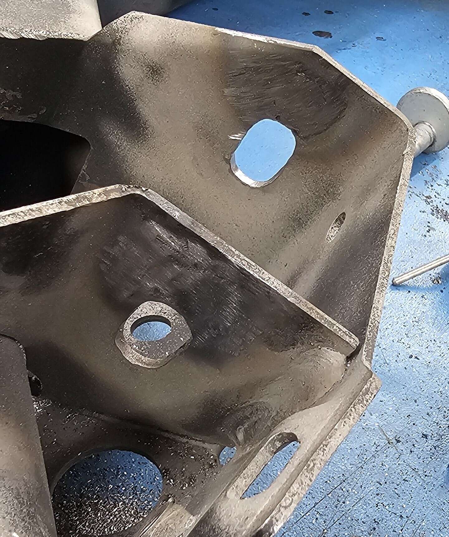
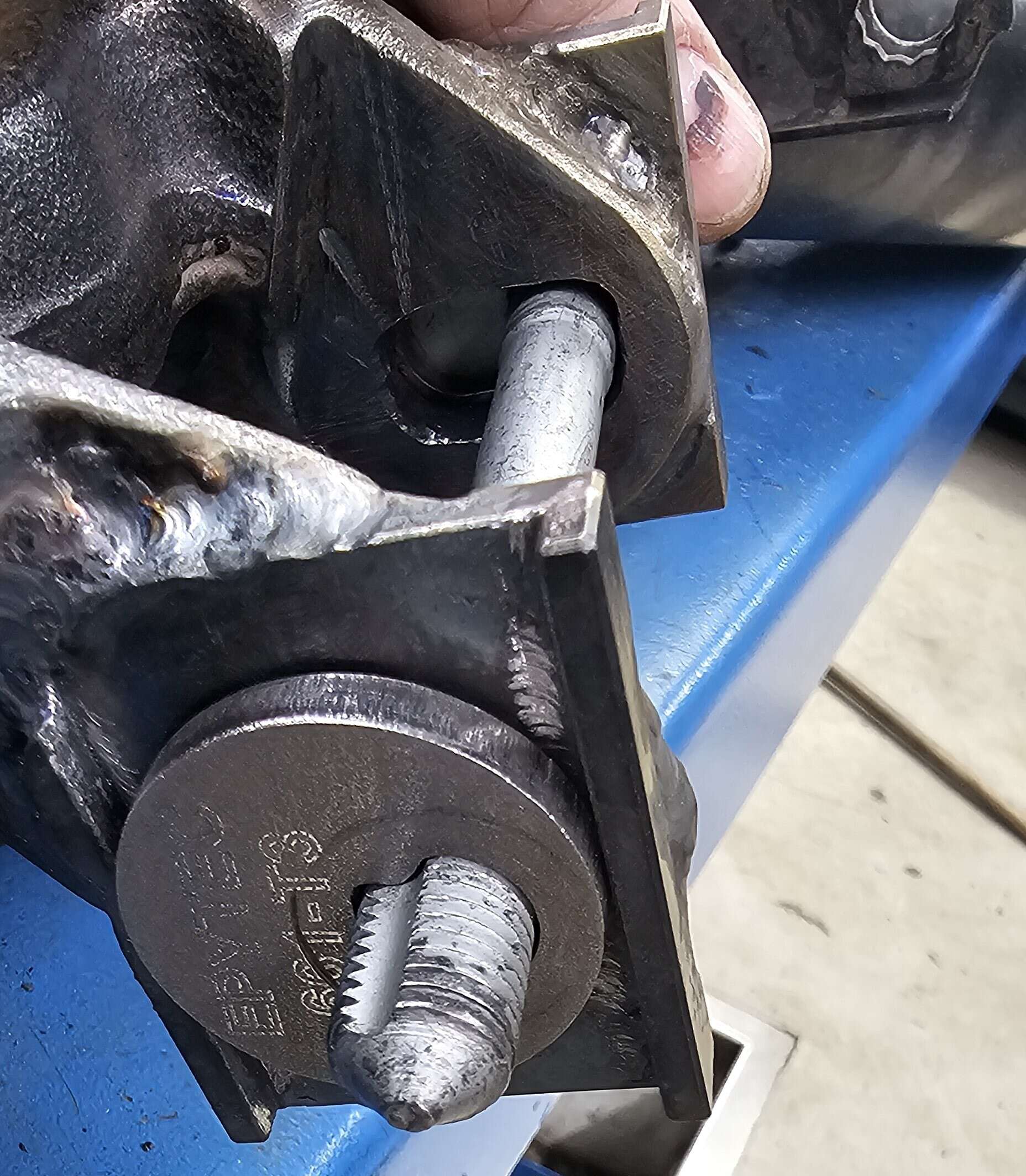
Step 8: Welding the camber adjustment plates to the inner mounting points of the control arm
After successful preparation, the camber adjustment plates can be welded. The same requirements apply to the outer plates as for the toe adjustment: careful alignment, spot-fixing and subsequent clean welding. The limited accessibility of the inner plates poses an additional challenge. A circumferential weld seam is not possible here - only three sides can be reached. The upper seam is particularly difficult to access and in this case was realised using the MIG welding process to ensure the necessary stability.
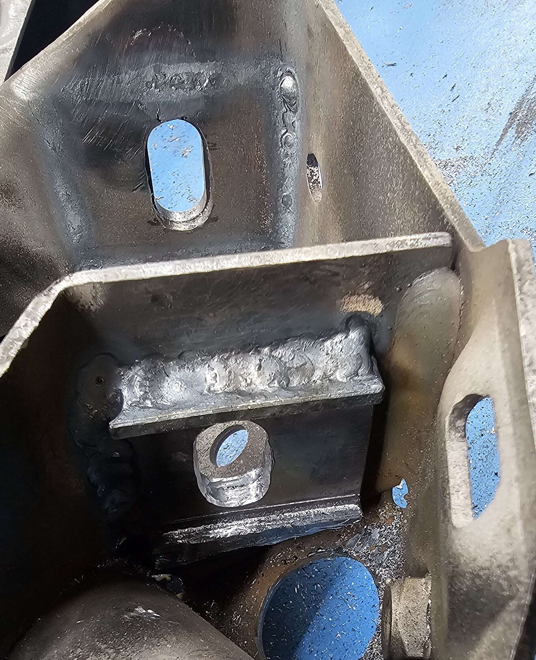
Step 9: Finishing and corrosion protection
After all panels have been welded, thorough finishing is required. The heat generated during welding can cause the panels to warp slightly. This can result in the eccentric screws and discs no longer being able to move freely. In this case, the inner contours of the slotted holes must be carefully reworked using a fine milling attachment. In addition, small chamfers of approx. 1.5 mm should be applied to all four internal plates so that the screws can rest on the entire surface. Finally, corrosion protection is applied. Here we recommend a high-quality powder coating, alternatively a robust paint finish is also possible.
Conclusion: Rewarding conversion for experienced mechanics
With the Epytec adjustment system for toe and camber, you can bring the wheel geometry back into the optimum range, even on heavily lowered Syncro vehicles. The conversion is complex, but with the right tools, technical understanding and patience, it can be done without any problems. The result: precise, sporty driving behaviour with a cleanly adjusted rear axle - just as it should be. Good luck with converting your own rear axle - and if you have any questions, we will of course be happy to help!
Error sources & troubleshooting
Grinding eccentric discs? → Panels warped - check the routing of the slotted holes and rework slightly if necessary.
Screw does not lie flat? → Forget the chamfer - add it later with a milling cutter.
Panels warped after welding? → Too few stitching points - fix evenly next time.
Is the wheel too far back in the wheel arch?→ Plate positioned too far back - relocate when reassembling.
Click here for the matching product

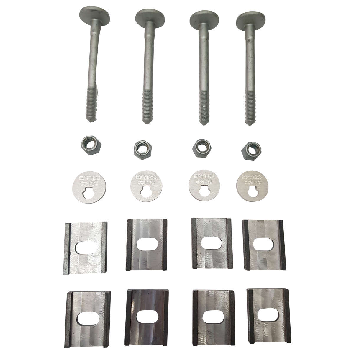
- ✓ -3.0 degrees to +3 degrees camber
- ✓ 8mm thickness
- ✓ suitable for Golf 2 3 Syncro
Safety & liability
⚠️ Wear safety goggles when drilling and grinding!
⚠️ Only work with approved welding equipment!
⚠️ Have wheel alignment carried out after the conversion!
Note: TÜV approval is required for this conversion. Consult your test centre!
FAQ for the installation instructions
Question 1
Can I do the conversion without welding skills?
Answer: No. As the panels are permanently connected to the subframe, professional welding is essential. If you lack the experience, you should have the conversion carried out by a specialist company.
Question
2
How does the track setting influence the driving behaviour?
Answer: Correct track adjustment improves driving stability and steering precision and significantly reduces tyre wear - a must, especially for lowered vehicles.
Question
3
Is the adjustment possible with standard wheels and lowering to 0° camber?
Answer: Depending on the lowering, almost 0° camber can be achieved with the adjustment plates. With extreme lowering, a slight negative camber remains for technical reasons.
Question
4
Does the subframe have to be repainted after the conversion?
Answer: Yes, absolutely. Without a suitable sealant (e.g. powder coating), there is an acute risk of corrosion due to welding.
Disclaimer
Please note that this installation is carried out at your own risk. Epytec accepts no liability for damage or injury resulting from following these instructions. Make sure that you understand all the steps and take the necessary safety measures.
And that's it! That's it! We hope that you have now successfully installed everything. If you have any questions or anything is unclear, please don't hesitate to contact us.
➡ Click here to go directly to the contact form (click here)
About Epytec
Epytec is a leading specialist in the manufacture of tuning adapters with more than 15 years of experience in the industry. Our products, which are manufactured entirely in Germany, stand for quality and innovation.
UOur highest quality standards and guaranteed TÜV registration ensure maximum safety.